Force lines in arches.
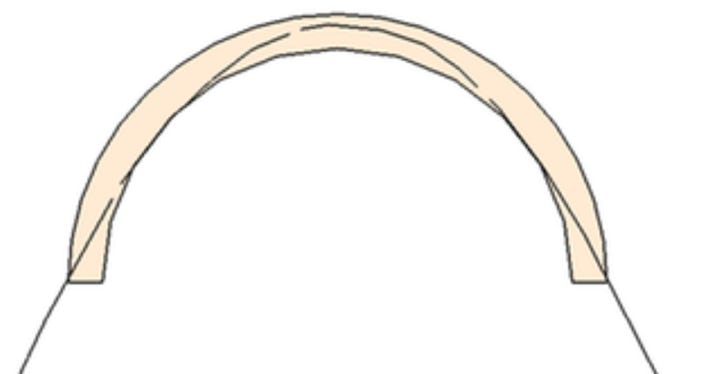
The semicircular arch in this sketch has been made increasingly thinner by increments until a point was reached where only one catenary curve would fit within it. The arch has a voussoir arch thickness about one-eighteenth of the span. In the 15th-century, Alberti recommended a ratio of 1: 15, yet he knew nothing of lines of thrust; his recommendation was empirical. Much later mathematical analyses by Couplet (Ref), Milankovitch (Ref) and then Heyman (Ref), all confirmed that true lines of thrust in such perfect arches require a minimum ratio of approximately 0.055 or 1:18.(width/span). This is the limit-arch and permits a force line which lies entirely within the masonry, and thereby implies that almost all stress will be compressive rather than tensile. ( A considerably larger safety margin is recommended in practice; the‘middle-third rule’).
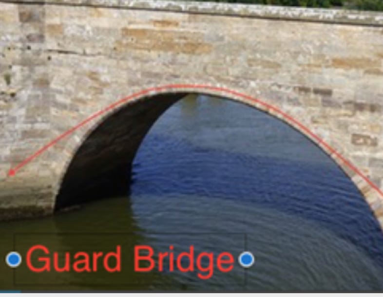
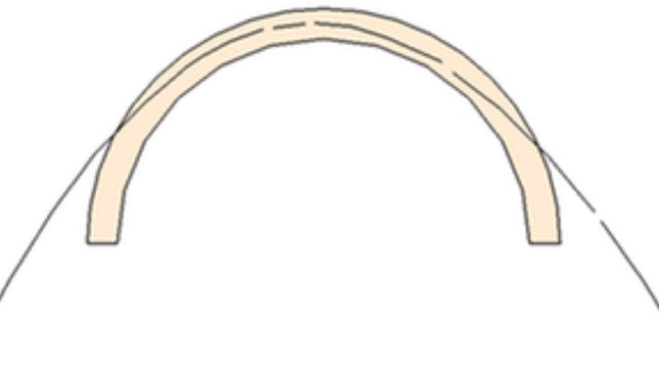
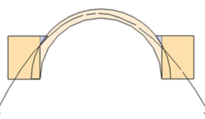
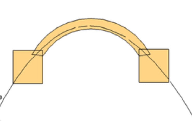
In fact, many semicircular bridges with a greater ratio than this are quite stable. For example, in Fife, Guard Bridge's semicircular arch has a ratio of almost 1:30, and yet it has been standing since the 16th century. As an explanation, a wider flatter parabola might be considered. Above left is a theoretic force line in which the upper part lies comfortably in the middle of the arch section; however, the lower parts of the force line will not do at all. The solution lies in moderately high abutments which will then contain the force line. (This whole proposition is really the wrong way round: abutments permit the masonry to contain a wider range of parabolas/ catenaries). There are further advantages here. The arch can remain slim but yet contain at least one suitable force line. Furthermore, the angle that the force line makes with each voussoir joint in the upper part of the arch is much more right-angular which confers additional strength and stability. The implication is that the parts of the voussoir arch below the top level of the abutments are really redundant and could be filled entirely by thicker abutments. The result is a raised (or stilted) segmental arch as in the above right railway bridge. The equilibrium of forces is effectively the same. The difference is cosmetic. Medieval masons had useful geometric rules of thumb for relating arch spans to the abutment thickness and span.
Why do we see so few catenary arches on buildings and bridges, today? In the early 20th century, when the Serbian engineer Milutin Milankovitch fully described the geometry of force lines, it was quickly acknowledged that catenary or parabolic architecture was expensive compared with rounded or segmental arches. The wooden centering was difficult to optimise as the radius of curvature varied through the arc; each voussoir required an individually tailored template. It was cheaper to use loading and buttressing abutments to manoeuvre the geometry to match a limit force-line. Furthermore, in the early 20th century ordinary masonry had ceased to be the only option: new reinforced materials with high tensile strength had arrived, This hugely reduced the inherent weakness of non-optimal shapes.
The optimal shape for a dome is also a catenary and it is Interesting that Inuit igloos are usually of that shape. Could it be that the ephemeral nature of the building-material fostered many rebuilds and a very early empirical solution?
Next: : Arch Shapes Early Building Previous: Arches.

Page last updated Apr 23